RÉSUMÉ EN ANGLAIS
TURBO-JET ENGINE
ENGINE COMPONENTS
All gas turbine engines are made up of the same basic components. However, the nomenclature used to describe each component varies from one manufacturer to another. Differences in nomenclature are reflected in the applicable maintenance manuals. The following discussion uses the terminology most commonly used in the industry.
There are seven basic sections within every gas turbine engine. They are the :
- air inlet ;
- compressor section ;
- combustion section ;
- turbine section ;
- exhaust section ;
- accessory section ;
- systems necessary for starting, lubrication, fuel supply, and auxiliary purposes, such as anti-icing, cooling, and pressurization.
Additional terms you often hear include hot section and cold section. A turbine engine's hot section includes the combustion, turbine, and exhaust sections. The cold section, on the other hand, includes the air inlet duct and the compressor section.
Vidéo de General Electric
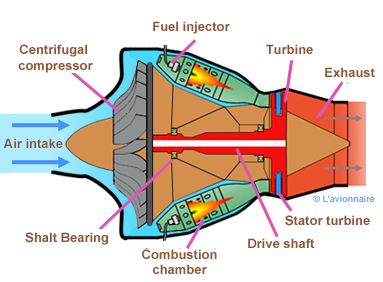
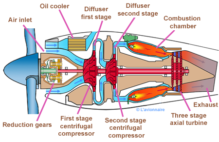
Single-stage centrifugal turbo-jet
A centrifugal compressor uses a series of blades mounted on a disk to throw incoming air outboard to a cylindrical shaft which funnels the air aft. The air is thus compressed and made ready for combustion. The compressor is driven by the turbine.
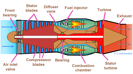
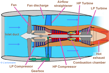
Single-spool axial flow turbo-jet
In the single-stage rotor turbine, the power is developed by one turbine rotor, and all engine-driven parts are driven by this single wheel. This arrangement is used on engines where the need for low weight and compactness predominates. This is the simplest version of the pure turbojet engine.
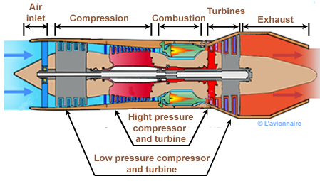
Twin-spool axial flow turbo-jet
In multiple spool engines, each spool has its own set of turbine stages. Each set of turbine stages turns the compressor attached to it. A multistage turbine is shown below.
Turbofan engine with separate nozzles fan and core
Most turbofan engines have two spools: low pressure (fan shaft a few stages of compression and the turbine to drive it) and high pressure (high pressure compressor shaft and high pressure turbine).
Turboprop engine
Turboprop is a gas turbine driving a propeller similar to those used with reciprocating engines, but with a larger gear box to get the greater reduction. Propeller and compressor may be driven by the same turbine or by separate turbines a compressor turbine and a load turbine, like for the turboshaft.
Compressor
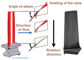
Rotor blades
A typical rotor blade showing twisted contour
The rotor blades are of airfoil section and usually designed to give a pressure gradient along their length to ensure that the air maintains a reasonably uniform axial velocity. The higher pressure towards the tip balances out the centrifugal action of the rotor on the airstream. To obtain these conditions, it is necessary to ’twist’ the blade from root to tip to give the correct angle of incidence at each point.
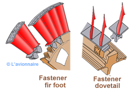
Methode of securing blades to disc
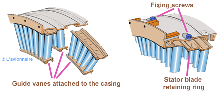
Stator blades
Methode of securing vanes to compressor casing
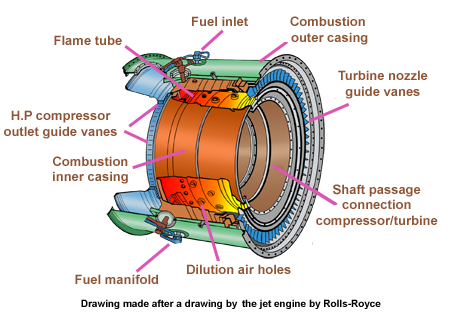
Combustion chamber
A combustion chamber must be capable of allowing fuel to burn efficiently over a wide range of operating conditions without incurring a large pressure loss. In addition, if flame extinction occurs, then it must be possible to relight. In performing these functions, the flame tube and spray nozzle atomizer components must be mechanically reliable.
There are three main types of combustion chamber in use for gas turbine engines. These are the multiple chamber, the tubo-annular chamber and the annular chamber.
Multiple combustion chamber
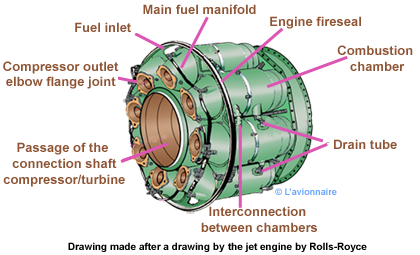
A separate combustion chamber

Annular combustion chamber
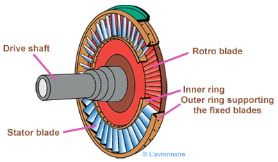
Turbine
A turbine stage consists of a fixed distributor or stator blade, followed by a moving blade or rotor.
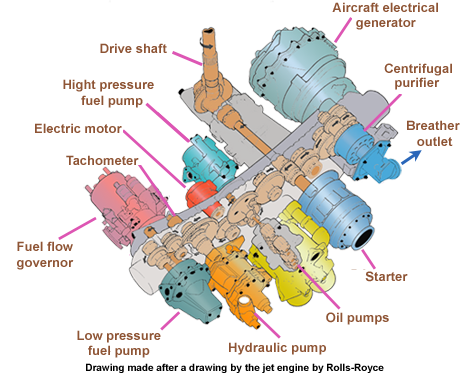
Accessory drives
The external gearbox contains the drives for the accessories, the drive from the starter and provides a mounting face for each accessory unit. Provision is also made for hand turning the engine, via the gearbox, for maintenance purposes. Figure below shows the accessory units that are typically found on an external gearbox.