RÉSUMÉ EN ANGLAIS
ENGINE INSTRUMENTS
Remote Sensing and Indication
It is often impractical or impossible to utilize direct reading gauges for information needed to be conveyed in the cockpit. Placing sensors at the most suitable location on the airframe or engine and transmitting the collected data electrically through wires to the displays in the cockpit is a widely used method of remote-sensing and indicating on aircraft.
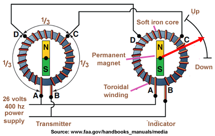
DC Selsyn Systems
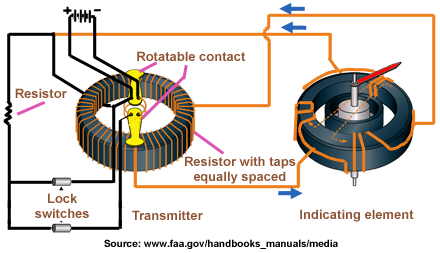
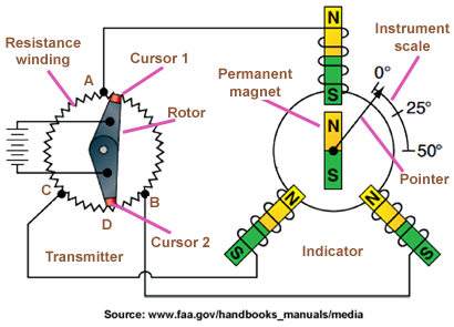
On aircraft with direct current (DC) electrical systems, the DC selsyn system is widely used. The selsyn system consists of a transmitter, an indicator, and connecting wires. The transmitter consists of a circular resistance winding and a rotatable contact arm. The rotatable contact arm turns on a shaft in the center of the resistance winding. The two ends of the arm are brushes and always touch the winding on opposite sides.
A lock switch circuit can be added to the basic DC selsyn synchro system when used to indicate landing gear position and up- and down-locked conditions on the same indicator.
DC Desyn Systems
The transmitter is identical to that of the Selsyn system.
- The receiver is almost identical to that of the Selsyn except that the stator is wound "star-shaped" instead of "triangular".
AC Magnesyn Systems
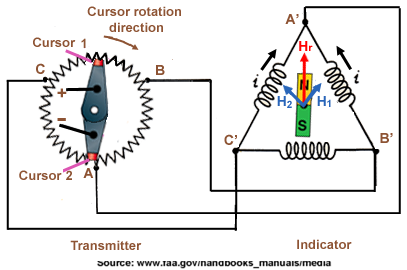
Aircraft with alternating current (AC) electrical power systems make use of autosyn or magnasysn synchro remote indicating systems. Both operate in a similar way to the DC selsyn system, except that AC power is used. Thus, they make use of electric induction, rather than resistance current flows defined by the rotor brushes. Magnasyn systems use permanent magnet rotors such a those found in the DC selsyn system.
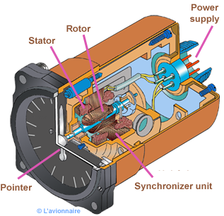
AC Autosyn Systems
Autosyn indicator receiver
Pressure measuring instruments
A number of instruments inform the pilot of the aircraft’s condition and flight situations through the measurement of pressure. Pressure-sensing instruments can be found in the flight group and the engine group. They can be either direct reading or remote sensing. These are some of the most critical instruments on the aircraft and must accurately inform the pilot to maintain safe operations.
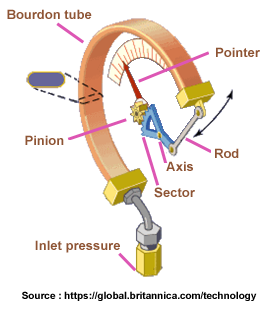
The Bourdon tube is one of the basic mechanisms for sensing pressure.
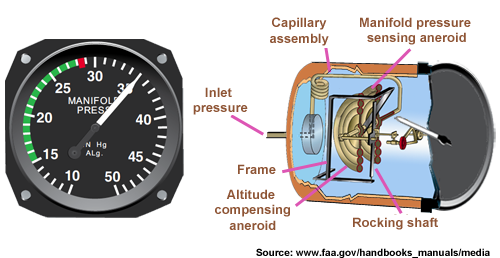
Intake pressure
In a GMP piston engine, the intake pressure in the manifold indicates the pressure of the air/fuel mixture in the intake pipes. This is an indication of the power developed by the engine.
An analog manifold pressure indicator instrument dial calibrated in inches of mercury.
Tachometers
The tachometer, or tach, is an instrument that indicates the speed of the crankshaft of a reciprocating engine. It can be a direct- or remote-indicating instrument, the dial of which is calibrated to indicate revolutions per minutes (rpm). On reciprocating engines, the tach is used to monitor engine power and to ensure the engine is operated within certified limits.
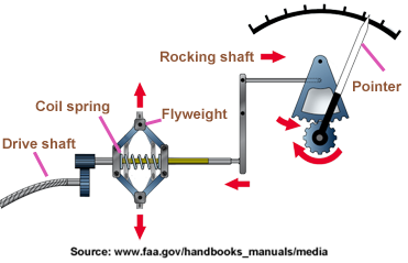
Mechanical tachometers
Mechanical tachometer indicating systems are found on small, single-engine light aircraft in which a short distance exists between the engine and the instrument panel. They consist of an indicator connected to the engine by a flexible drive shaft. The drive shaft is geared into the engine so that when the engine turns, so does the shaft.
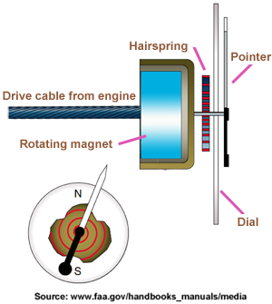
Electric tachometers
It is not practical to use a mechanical linkage between the engine and the speedometer on aircraft whose engines are not mounted in the fuselage just forward of the instrument panel. The use of electric tachometers allows for greater accuracy while reducing maintenance.
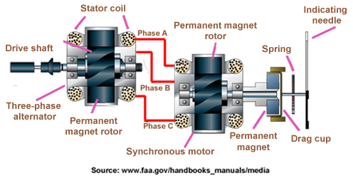
An electric tachometer system with synchronous motors and a drag cup indicator.
Fuel flowmeters
A fuel flowmeter indicates an engine’s fuel use in real time. This can be useful to the pilot for ascertaining engine performance and for flight planning calculations. The types of fuel flow meter used on an aircraft depends primarily on the powerplant being used and the associated fuel systemn.
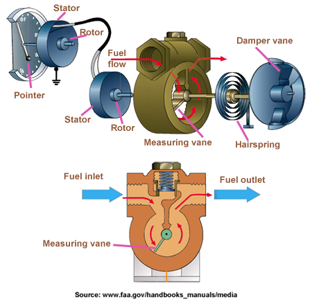
A vane-type fuel flow meter. Greater flow volume increases deflection of the vane against a calibrated spring. An autosyn transmitter replicates the vane shaft rotation on the cockpit indicator that is calibrated in gallons or pounds of fuel flow per hour.
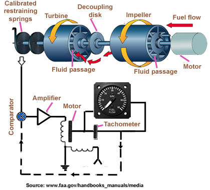
A mass flow fuel flow indicating system used on turbine-engine aircraft uses the direct relationship between viscosity and mass to display fuel flow in pounds per hour.
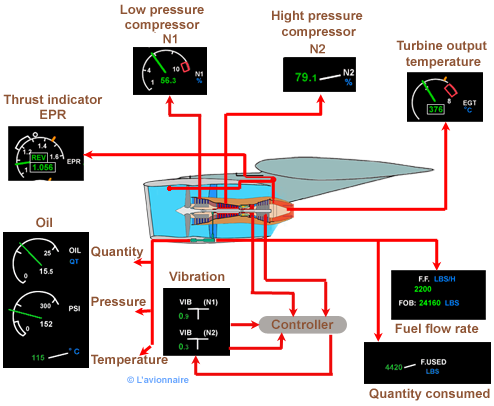
Display of Airbus A320 engine parameters.